
First Published: December 23, 2019
Last Update: December 31, 2019
This is the first in a series of three planned articles discussing the modification of Yaesu DR-1X repeaters for solid, link-ready analog FM or as a multi-mode digital voice repeater. The planned articles are:
- Yaesu DR-1X Repeater Modifications: Common Concerns
- DR-1X Repeater Mods for Analog + Allstar
- DR-1X Repeater Mods for Digital Voice
Introduction
This article will cover various considerations about the Yaesu DR-1X that would be common to any deployment scenario with an external controller, analog (such as Allstar) or digital (such as Pi-Star). All of the items below concern successful operations with either setup.
Setup-specific issues will be covered in the mode-specific articles.
Type of DR-1X is Important!
Everything in these series of articles is discussing the original Yaesu DR-1X repeater units. There are three versions of the Yaesu DR-series repeaters:
- Original Yaesu DR-1X
- “Factory Refurb” DR-1X or the “second generation” DR-1X (called DR-1XFR)
- DR-2X
Only the original DR-1X is suitable for modification and enhancement!
The DR-1XFR has firmware enhancements/changes that are incompatible with reasonable modifications to the repeaters. This author has never used a DR-2X but by all reports, the are completely locked down by Yaesu against modifications or outboard digital controllers.
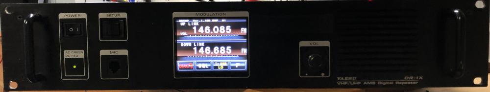
A DR-2X is obvious by the name plate. However questions arise about the various versions of the DR-1X, namely, how do you tell? It’s actually quite easy. The original Yaeseu DR-1X that was not factory modified or was of the second generation has a firmware version of 1.00 or 1.10 followed by a single letter. Examples of known firmware include 1.00a, 1.00n, 1.00t, 1.10de, 1.10j, and 1.10q. The firmware version is displayed across the top of the first setup screen where the frequencies are programmed.
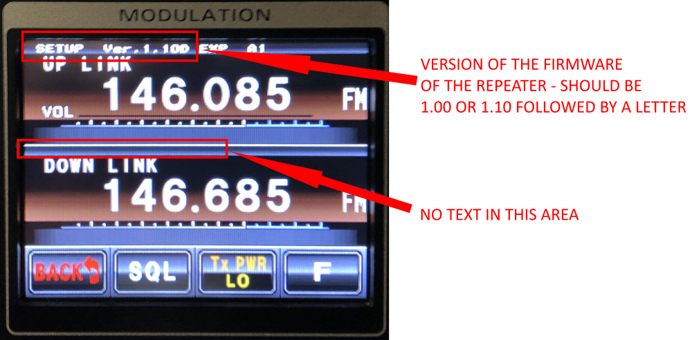
Firmware string that lists other versions (e.g. 1.201) and, more importantly, lists a panel and DSP version in a line between the transmit and receive frequencies is a DR-1XFR and is not capable of modification for digital use.
Firmware Updates
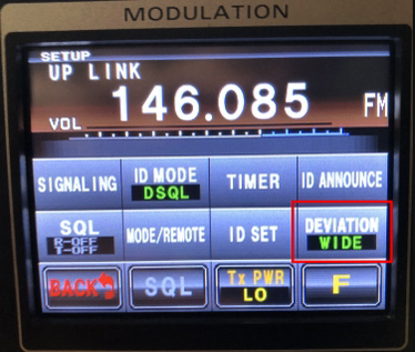
To accomplish any of these modifications, the DR-1X must be running a version of the firmware that enables or allows for “Wide-FM Deviation” mode of operation. For firmware V1.00a or V1.00f, upgrade to V1.00n. V1.00n enables “Wide FM” operation without a selector or configuration mode.
All versions of V1.10 appear to have selectable wide/narrow deviation in the control panel despite the release notes stating that V1.10q is necessary. If for some reason your V1.10 unit does not have selectable wide/narrow, upgrade to V1.10q.
All firmware upgrades are found on yaesu.com at https://www.yaesu.com/indexVS.cfm?cmd=DisplayProducts&ProdCatID=249&encProdID=F331C35D03DC8A6B3151A09A7875712E&DivisionID=65&isArchived=0 and then click on the Files tab.
Why Modify a DR-1X?
The DR-1X had a mixed history after its release. The DR-1X was released at a very low price point to help encourage the adoption of the Yaesu System Fusion system. Clubs could obtain a new DR-1X for a low as $400 based on various programs and incentives that included no selling the repeater for a period of time and enabling YSF within a year of purchase. The DR-1X repeater is a set of modified FTM-400DR radios with additional DSP and repeater controller functionality grafted in. The repeaters were designed and built around Yaesu’s Auto Mode Select (AMS) strategy that would switch modes based on receiving analog FM or C4FM signals. Thus there are many DR-1X repeaters around, both deployed and un-deployed.
However some of the choices that went into the design and concept yielded mixed results. There were initial problems with the units blowing out the finals in the transmit when being run at full power which eventually caused Yaesu to stop marketing them as 50W at continuous duty. The other main issue is that the squelch is poor. This is important when dealing with weak or marginal signals. With a poor squelch, weak signals that would otherwise be readable are clipped out too quickly. The squelch is tunable like on most radios, but opening up the squelch more will result in long, loud squelch tails from strong signals. One of the original primary reasons to modify the DR-1X was to fix this problem.
The other reason to modify the DR-1X is to support digital voice modes (or support them better). With the emergence of Pi-Star and repeater-quality digital modems (such as the excellent STM32-DVM from Repeater Builder), repeater owners wanted to support more modes. The DR-1X while supporting C4FM/YSF on the local machine did not support the WIRES-X linking ability out of the box – it required a second piece of hardware. In most deployments, the DR-1X was set for AMS mode in (i.e. FM or C4FM in) and fixed analog FM out. Linking was rarely ever hooked up. So the ability to add a Pi-Star controller became a very compelling thing to do.
DR-1X Controller Port
The DR-1X comes with an outboard D-Sub DE-15 socket connector with all the items necessary to hook into and control the DR-1X radios, bypassing all of the internal repeater items. The pinout is as follows:
| Pin | Description |
|---|---|
| 1 | Operating Mode Ground = Remote Control Float = Local Control |
| 2 | PTT Input from external controller Transmit on pull to ground |
| 3 | CTCSS/DCS Detection Output Ground = Decoded Float = Undecoded |
| 4 | Squelch Detect (noise only, not CTCSS/DCS decode) Ground = Squelch Open Float = Squelch Closed |
| 5 | Ground |
| 6 | Tone In Input for sub-audible tone, CTCSS or DCS, to be mixed with the audio received on pin 7 during external PTT control (i.e. Pin 1 = GND + Pin 2 = GND) |
| 7 | Audio In |
| 8 | Discriminator Audio Out (i.e. not de-emphasized audio out) |
| 9 | Audio Out (i.e. de-emphasized audio output) |
| 10 | Ground |
| 11 | Logic Port #1 for Mode Control |
| 12 | Logic Port #2 for Mode Control |
| 13 | Logic Port #3 for Mode Control |
| 14 | Logic Port#4 for Mode Control |
| 15 | VCC Power Supply Power supply output voltage (usually ~14.0 VDC) at 3A fused |
See the Yaseu DR-1X Operating Manual page 34 for more details.
Pins 11 and 12 are the external logic pins that are used to fix the operating mode. For external controllers, you want to fix the operating mode as FM Fixed for both receive and transmit. This is true whether you plan to do analog FM or digital voice FM from an external controller. The Yaesu manual lists all possible combinations, but to fix the mode to FM analog pull pin 11 to ground and float pin 12.
To ensure consistent operation and avoid DR-1X lock-up, make sure that all pins that enable remote control or control mode are connected to the same ground. To properly enable an external controller, make sure pins 1, 5, 10, and 11 are all bonded together and then used to feed the ground of all downstream components.
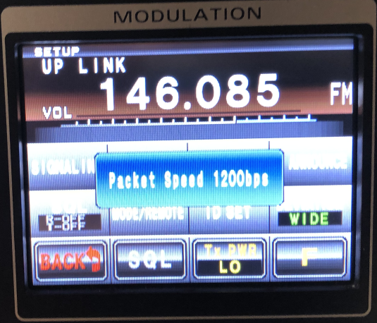
Packet Speed Setting
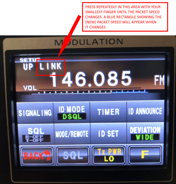
The Packet Speed setting, for the purposes of this set of articles, matters only in that the use of the 1200bps setting runs audio through the DSP processor and provides a 6dB gain on the audio level. The use of the 9600bps settings bypasses the processing. For digital modes, you must use the 9600bps setting to avoid the DSP mangling the signal. For analog use, 1200bps will probably result in better quality audio but testing for each setup will be required.
Setting the Packet Speed is a weird operation as there is no config panel button for it. Using your smallest finger, repeatedly press around the letters “LIN” of the line “UP LINK” above the receive frequency in the second setup menu. When the packet speed changes, a blue rectangle will appear in the middle of the screen showing the new speed.
(Added in 2023) One important aspect of this setting is that when “Packet Speed” is set to 9600bps, then the audio into the transmitter will bypass the pre-emphasis stage of the radio. In that case, the audio supplied in on the “AUD IN” pin 7 must already be pre-emphasized for FM analog voice transmissions. Essentially the “9600bps” is the concept of “audio in – audio out”.
CTCSS/DCS Detection Pin 3 Without Tone/TSQL Set
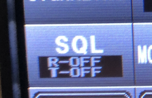
It’s important to understand the interaction of the CTCSS/DCS detection pin 3 on the external controller connector and the DR-1X when there is no Tone set in the control panel. If “SQL” is set to R-OFF T-OFF (see image at right) then pin 3 acts like a COS detection line. When a signal is received, pin 3 will go low regardless of the lack of a CTCSS/DCS decode or setting.
When using a digital modem such as the STM32-DVM, premade cables have pin 3 wired through for COS detection. This commonly used for combining analog and digital modes and will cause boards such as the STM32-DVM to lock out the transmitter believing an analog transmission is in progress. If you have no intention of supporting dual analog and digital modes on the same repeater, make sure that pin 3 is not connected to the modem’s COS detection line. Alternatively, set the DR-1X to an obscure high DCS code (e.g. DCS 411) so that the DR-1X never properly decodes anything.
This could also be a problem with an external analog controller depending on the configuration and wiring.
CTCSS/DCS Encoding with External Audio from a Controller
The DR-1X, when transmitting audio from an external source and triggered by the external PTT, will not mix in a CTCSS or DCS sub-audible signal from the onboard encoder regardless of setting of the “SQL T” menu option. That is to say, when pin 1 is pulled low for PTT, the audio is sent directly as provided by pin 7 – the DR-1X’s onboard CTCSS/DCS encode is bypassed. Thus if the DR-1X’s internal CTCSS decoder is used to open the repeater, Tone Squelch for clients of the repeater cannot be used from the onboard encoder. DCS mode is impossible in this configuration because DCS requires both a decode and an encode to function. There are two ways to encode CTCSS or DCS when using external audio.
The first is to use an outboard CTCSS or DCS encoder/decoder board such as the Com-Spec DCS-23 for DCS or the Com-Spec TS-64WDS for CTCSS. The CTCSS/DCS board listens to the discriminator audio for valid CTCSS/DCS and then signals a valid decode to the external controller’s CTCSS detection pin and provides high-pass filtered audio to the external controller. A dual encode/decode board can then be used to inject coding into the DR-1X transmit audio by supplying the sub-audible signal on pin 6 of the external controller port. If using DCS, you must run the PTT through the DCS board so that the PTT signal can be monitored to send the “close” DCS coding burst.
The second is to do all decoding and encoding within the external controller. For example, an Allstar-based controller can do both CTCSS decode and encode using the “usbradio” mode. It will provide the sub-audible coding directly in the audio output stream.
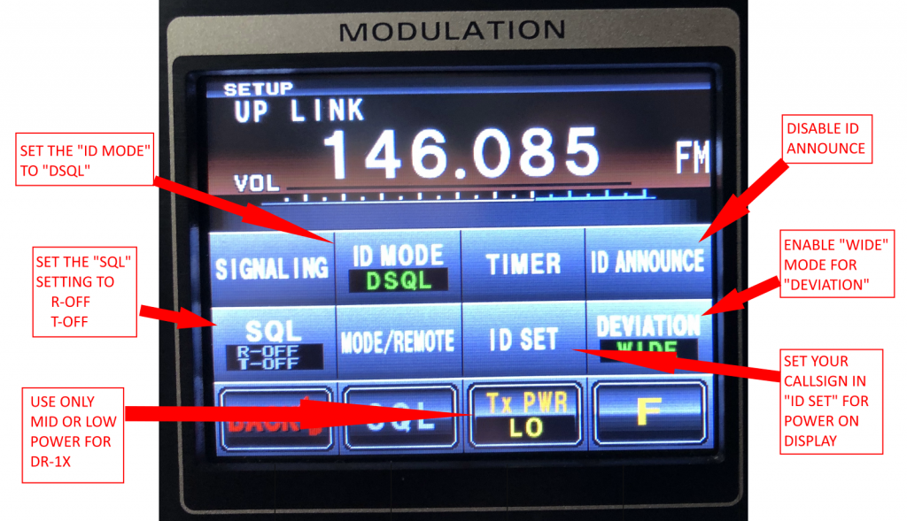
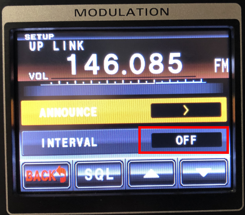
Repeater ID
In most cases, you will want the repeater ID to be handled by the external controller. Make sure that ID is disabled under the setup menu. Additionally, make sure that the DG-ID is set to “DSQL”.
Cooling
It’s important to keep the air flowing through your DR-1X, especially if you’re going to run it on Mid power or (not recommended) High power for anything approaching continuous duty. Here are some recommendations for optimizing the cooling:
- Make sure that the temperature sensor package is working for the internal fan. Ensure that the sensor will trigger and turn the internal fan on. If it’s not, replace it or simply hard-wire the internal fan to run continuously.
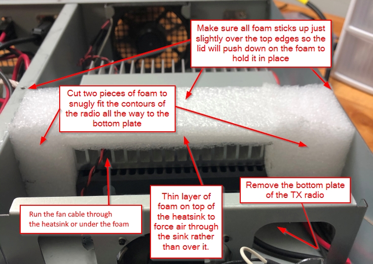
- Remove the bottom cover of the transmit radio. The transmit radio’s body has both halves of the FTM-400 cover attached by default. However the bottom cover is unnecessary and can impede airflow. Completely remove the TX radio, remove the bottom cover, and re-install the TX radio.
- Replace the air dam with denser material and extend it down both sides. A thick packing foam works well for this. See the picture below. Even if you don’t want to do this, at least make sure that the original factory air dam is actually installed. Many people have taken off the cover and not replaced it or damaged it. Both DR-1Xs this author has refurbished had them missing.
Conclusion
Above are all of the common issues for modifications and external controllers for a Yaesu DR-1X. Specific concerns and designs for analog external controllers and digital controllers will be presented in separate articles.


