This is the second in a series of three planned articles discussing the modification of Yaesu DR-1X repeaters for solid, link-ready analog FM or as a multi-mode digital voice repeater. The planned articles are:
- Yaesu DR-1X Repeater Modifications: Common Concerns
- DR-1X Repeater Mods for Analog + Allstar
- DR-1X Repeater Mods for Digital Voice
Introduction
This article outlines how to add an external controller to a Yaesu DR-1X repeater to improve its squelch operation and add Allstar and Echolink services.. If you haven’t read it yet, please read Yaesu DR-1X Repeater Modification: Common Concerns first. It contains important information to understand before undertaking a conversion.
Aside from adding Allstar and Echolink capabilities, the main reason to replace the controller logic of the DR-1X with an external controller is to deal with the poor squelch operation of the DR-1X. This is important when dealing with weak or marginal signals. With a poor squelch, weak signals that would otherwise be readable are clipped out too quickly. The squelch is tunable like on most radios, but opening up the squelch more will result in long, loud squelch tails from strong signals. One of the original primary reasons to modify the DR-1X was to fix this problem and balance out the operation of the radios.
Theory of Operation
This outlines connecting a home-brew controller to a DR-1X. There are obvious commercial choices such as the S-COM 7330 that integrate and work well with the DR-1X. This article is to explain home-brew controllers using common parts.
Design
A schematic is worth a thousand words (click to enlarge)

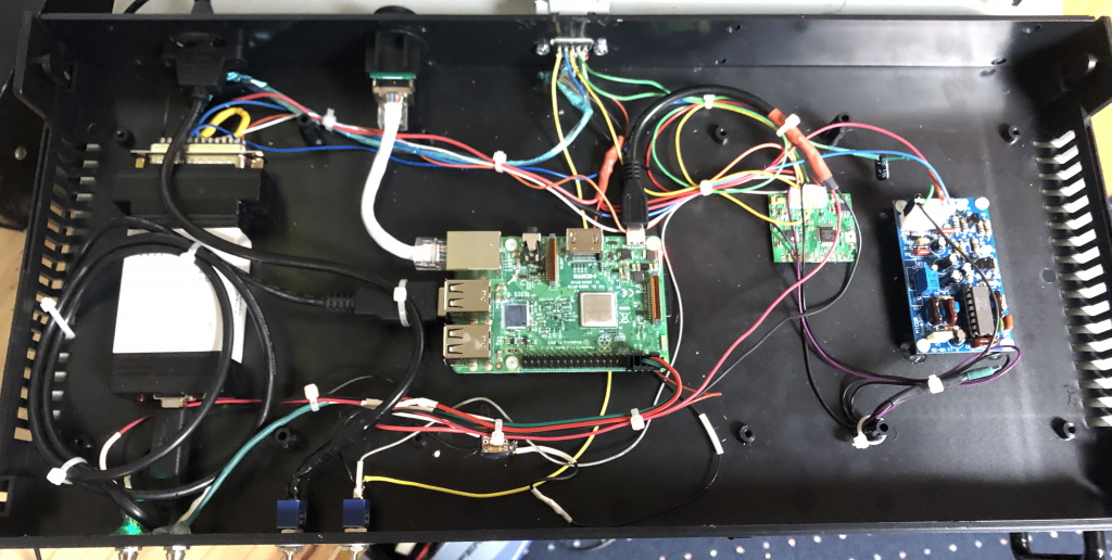
As detailed in Yaesu DR-1X Repeater Modification: Common Concerns, the DE-15 port on the rear of the unit exposes everything you need to put in a quality external controller. The system above uses a DMI URIx audio interface fed by a Masters Communication MS-25 squelch board and a Comm-Spec DCS-23 decoder/encoder board. Power for the DCS-23 and MS-25 boards is supplied by the +VDC line from pin 15 of the DR-1X external port.
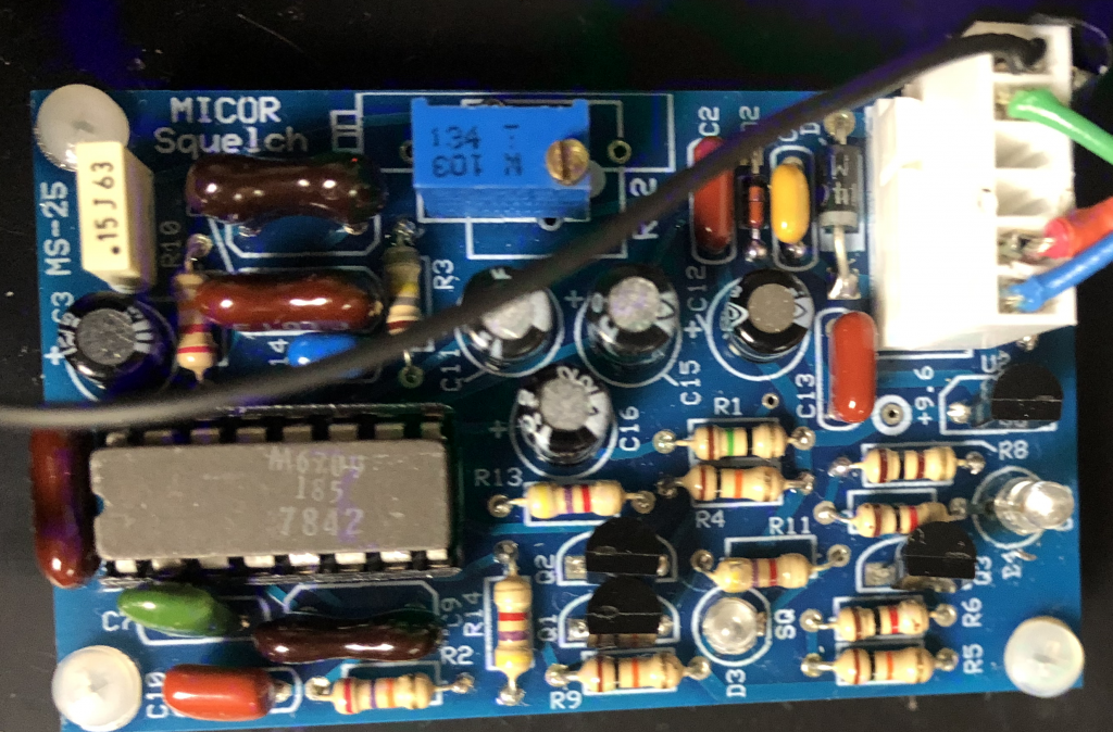
The Masters Communication MS-25 is used because it uses the benchmark Motorola MICOR M6709 chip. This board is the current gold standard in tune-able audio squelch boards. The MS-25 board listens to the audio from the DR-1X receive radio and signals the URIx’s COR_DET line. The MS-25 has the option to signal high or low. This design is signaling COR/COS detect high because of the construction of the circuits. Whenever the +12V power is removed from the system (i.e. turning the DR-1X off), the COS (NOT) line (i.e. active low) becomes a sink to ground always keying the COR_DET line on the URIx.
This Comm-Spec DCS-23 was used because DCS is a great replacement for CTCSS due to a “reverse burst” being part of the DCS standard. In this design, the PTT out from the URIx is intercepted by the DCS-23 board and then passed to the DR-1X. When the PTT line is dropped from the URIx, signaling the end of a transmission from controller, the DCS board inserts a delay in the PTT drop and changes the DCS coding signal to send the “reverse burst” code telling the radios receiving from the repeater that the signal is ending and to close the squelch. This complete eliminates the squelch tail found on systems using CTCSS. Most common radios support DCS (“DTCS” or “DPL” depending on brand) and is programmed just like CTCSS/PL. Some plans for outboard controllers found online do not intercept the PTT line coming back out of the URIx. However its imperative to do that so the DCS board can generate the “Reverse burst” tone and close the radio prior to dropping the carrier.
The audio from the receive radio is filtered through the DCS-23 board to remove the DCS sub-audible tones and passed into the URIx. The DCS-23 board also sends its signal to the CTCSS_DET line on the URIx. The audio is also split off before the DCS-23 board to the MS-25 squelch board.
Parts List
The following parts are used to create the minimum viable controller.
| Part | URL | Cost | Notes |
|---|---|---|---|
| Raspberry Pi 3B Kit: Raspberry Pi 3B Heatsinks Power Supply | https://amazon.com/dp/B01C6EQNNK | $50 | |
| Samsung EVO Select 32GB MicroSDXC | https://amazon.com/dp/B06XWN9Q99 | $6.50 | Note: Get this exact card; don’t cheap out on this or use one you already have |
| Masters Communication MS-25 | https://www.masterscommunications.com/products/squelch/ms25.html | $50 + S/H | |
| Comm-Spec DCS-23 | https://com-spec.com//tone_signaling/ts_order.html | $69.96 + S/H | |
| D-SUB DE-15 Plug | https://smile.amazon.com/gp/product/B07F9S61QT | $11.59 | |
| Sparkfun Resistor Kit | https://www.sparkfun.com/products/10969 | $7.95 + S/H | |
| Sparkfun Capacitor Kit | https://www.sparkfun.com/products/13698 | $7.95 + S/H |
If you want to put things in a nice case, the following parts may be helpful.
| Part | URL | Price |
|---|---|---|
| 1U ABS Plastic Rackmount Case | https://www.mpja.com/Rack-Mount-Case-ABS-Plastic-1U/productinfo/17086+BX/ | $24.95 + S/H |
| RJ-45 Case Pass-Through | https://smile.amazon.com/gp/product/B072FG6R66 | $17.53 |
| Micro USB Panel-mountable Extension | https://smile.amazon.com/gp/product/B072FG6R66 | $5.29 |
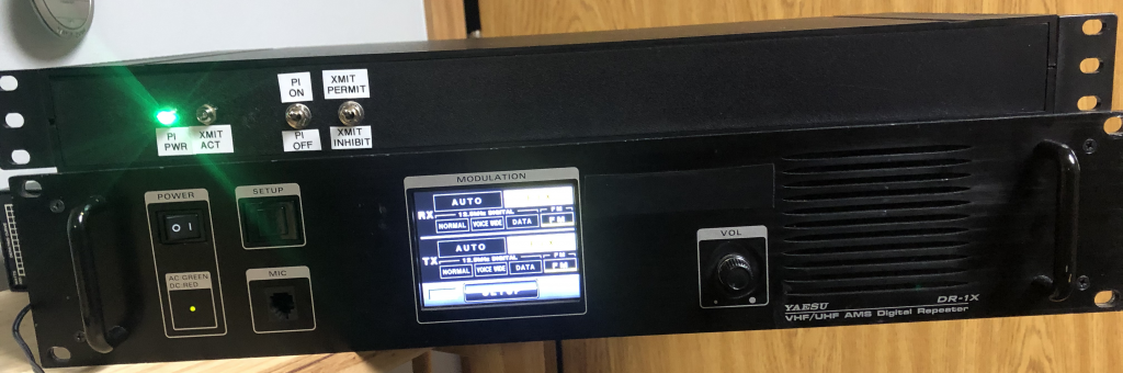
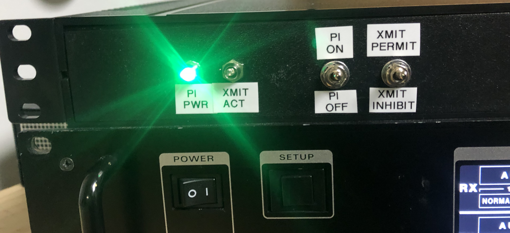
It’s also possible to get creative and add additional items. In the complete build pictured below, I included LED lights for power and PTT and switches to control the Pi power and to inhibit TX.
Assembly
Assemble everything according to the schematic above.
DR-1X Setup
Before plugging in the external controller cable, set the transmit and received frequencies. Then additionally set the following:
Ensure Packet Speed Is Set to 9600
Follow the directions on the page Yaesu DR-1X Repeater Modification: Common Concerns under Packet Speed Setting. Make sure the Packet Speed is set to 9600bps. This is important to bypass the DSP module in the DR-1X.
Ensure the DR-1X is in Wide Deviation Mode
If your DR-1X supports a toggle button on the second Configuration panel, make sure that the Deviation = WIDE mode is selected. Not all DR-1X firmware versions allow selecting this. See Firmware Updates in Yaesu DR-1X Repeater Modification: Common Concerns for how to make sure your repeater is running a firmware with Wide Deviation mode.
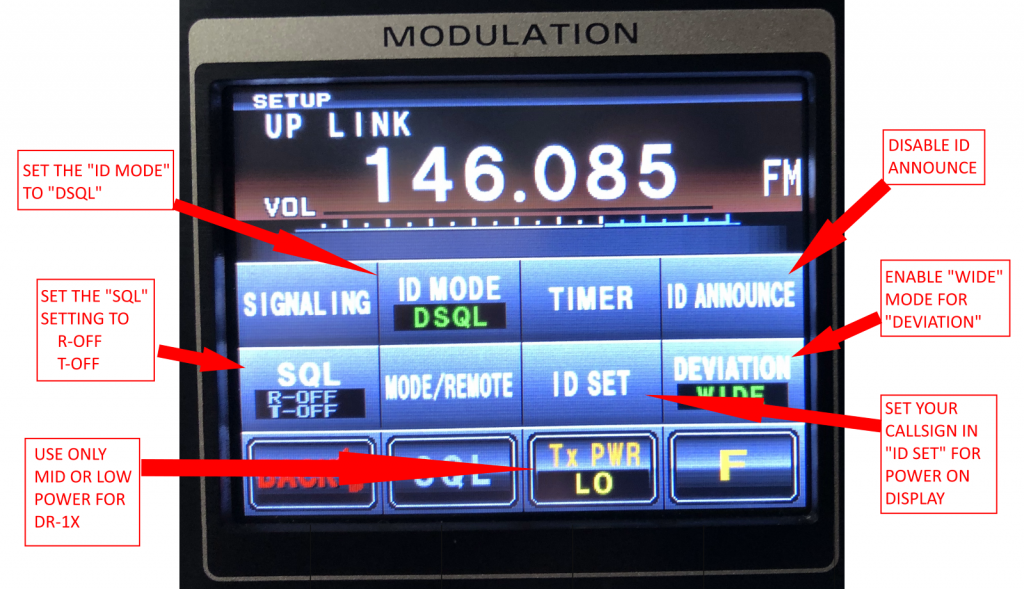
Other Settings
- Make sure that Tone and Tone Squelch are disabled
- Make sure that the ID function is OFF – Allstar takes care of the ID for you
- Make sure that there’s no YSF DG_ID set – set it to “DSQL”
- Choose Lo or Mid power – do not use High power – the DR-1X cannot take that transmit level long
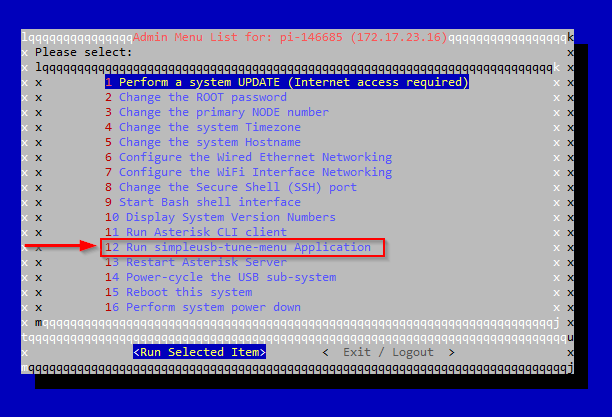
HamVOIP
The HamVOIP distribution of Allstar is the easiest to setup on a Raspberry Pi. The directions are fairly comprehensive. Configuring Allstar is beyond the scope of this tutorial. However here are the settings needed in the Simple USB Tune menu.
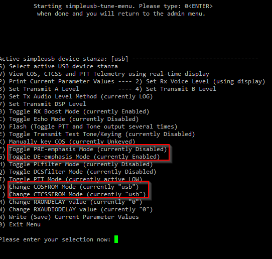
- COSFROM Mode needs to be “usb” (i.e. “active high”)
- CTCSSFROM Mode needs to be “usb” (i.e. “active high”)
- Disable PRE-emphasis mode
- Enable DE-emphasis mode
You will also need to test the “Set Rx Voice Level” and “Set Transmit DSP Level”. Currently the default of 500 for Rx Voice Level and a Transmit DSP Level of 750 seem to work best with this stack.
Completed Repeater Controller